14
2025.1
author
88
Reading volume
OneThe concept of surface roughness
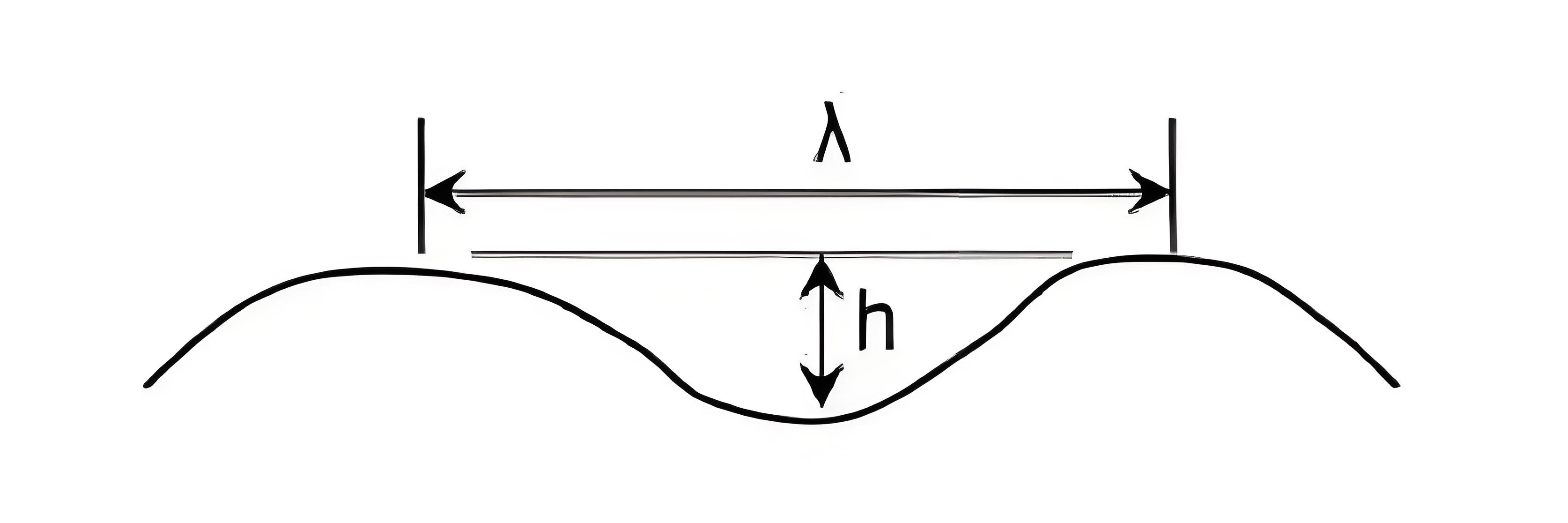
Surface roughness reflects microscopic geometry errors on the surface of the part being machined. It is mainly formed by the friction between the surface of the tool and the part during the machining process, the plastic deformation of the surface metal layer during cutting separation, and the high-frequency vibration of the process system. Surface roughness is different from the surface macro geometric error mainly caused by the error of the geometric accuracy of the machine tool: it is also different from the surface wave between the macro and micro geometry errors mainly caused by the vibration, heat, rotary body imbalance and other factors of the machine tool-tool-workpiece system during the machining process, but refers to the microscopic geometry characteristics composed of small spacing and peaks and valleys on the machined surface.
There are no strict standards for the three classifications of surface roughness, surface wave and shape error. It is usually divided according to the waveform fluctuation spacing into and amplitude h-ratio. If it is less than 40, it is the surface roughness, and if it is 40-1000, it is the surface wave. If it is greater than 1000, it is a shape error.
TwoThe effect of surface roughness on the part
1. Impact on friction and wear. The rougher the surface, the faster the wear;
2. Influence on the nature of cooperation. The rougher the surface, the more unstable the fit;
3. Effect on fatigue strength. The rougher the surface, the lower the fatigue strength;
4. Influence on contact stiffness. The rougher the surface, the lower the contact stiffness;
5. Impact on corrosion resistance. The rougher the surface, the easier it is to cause surface rust;
6. It has a great impact on sealing, appearance quality and surface coating.
ThreeThe main parameters of surface roughness are evaluated
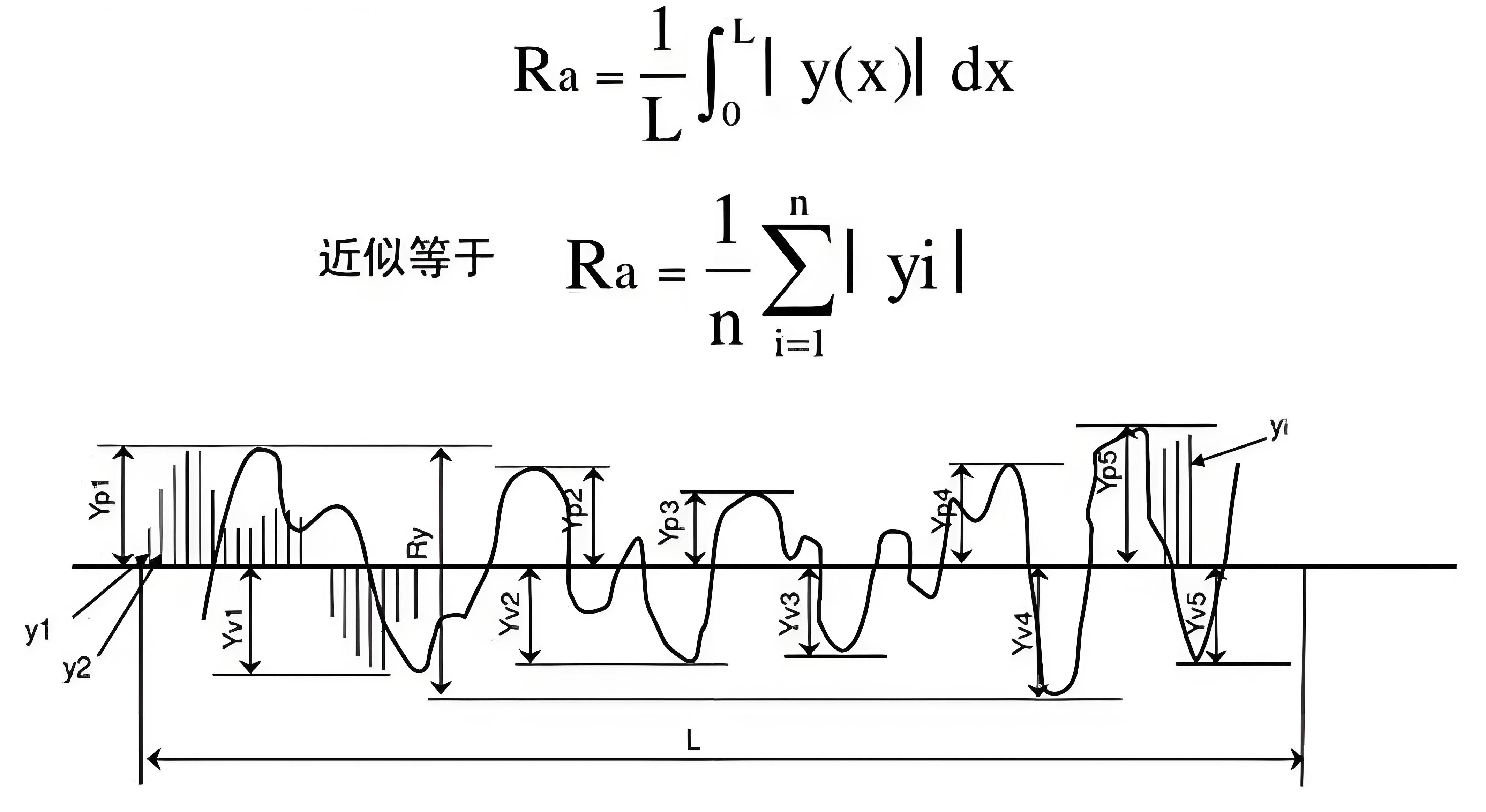
Contour arithmetic mean deviation Ra
The arithmetic mean of the absolute value of the distance from each point to the reference line Yi on the actual contour of the measured length within the sampling length.
FourSurface characteristics and applications of surface roughness
Ra Series 1: 0.012, 0.025, 0.050, 0.100, 0.20, 0.40, 0.80, 1.6, 3.2, 6.3, 12.5, 25, 50, 100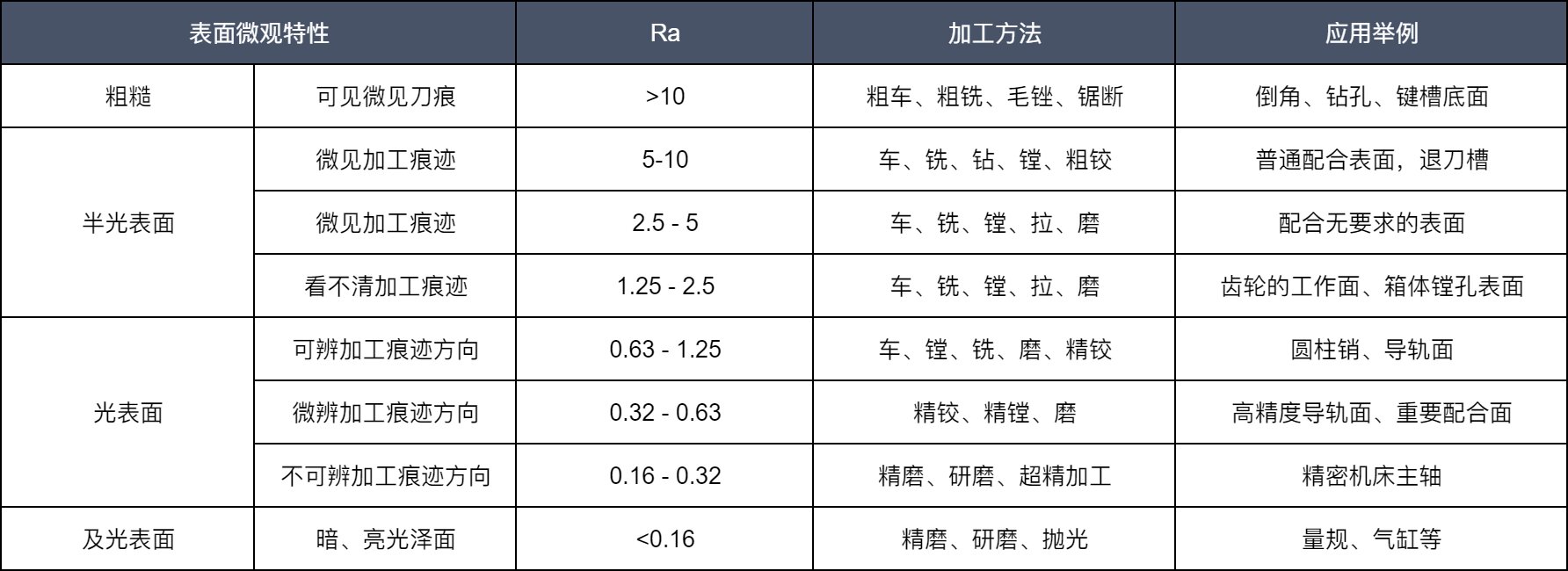
Note: When Ra=0.80, ordinary turning and milling are already difficult to process
FiveDetection of surface roughness
1. Comparative method:Comparison of the measured surface with the roughness sample;
2. Light cutting method:photocut microscope;
3. Interference method:interference microscopy;
4. Contour method:motorized profiler;
5. Scanning method:Laser or IR scanning contour scanner.
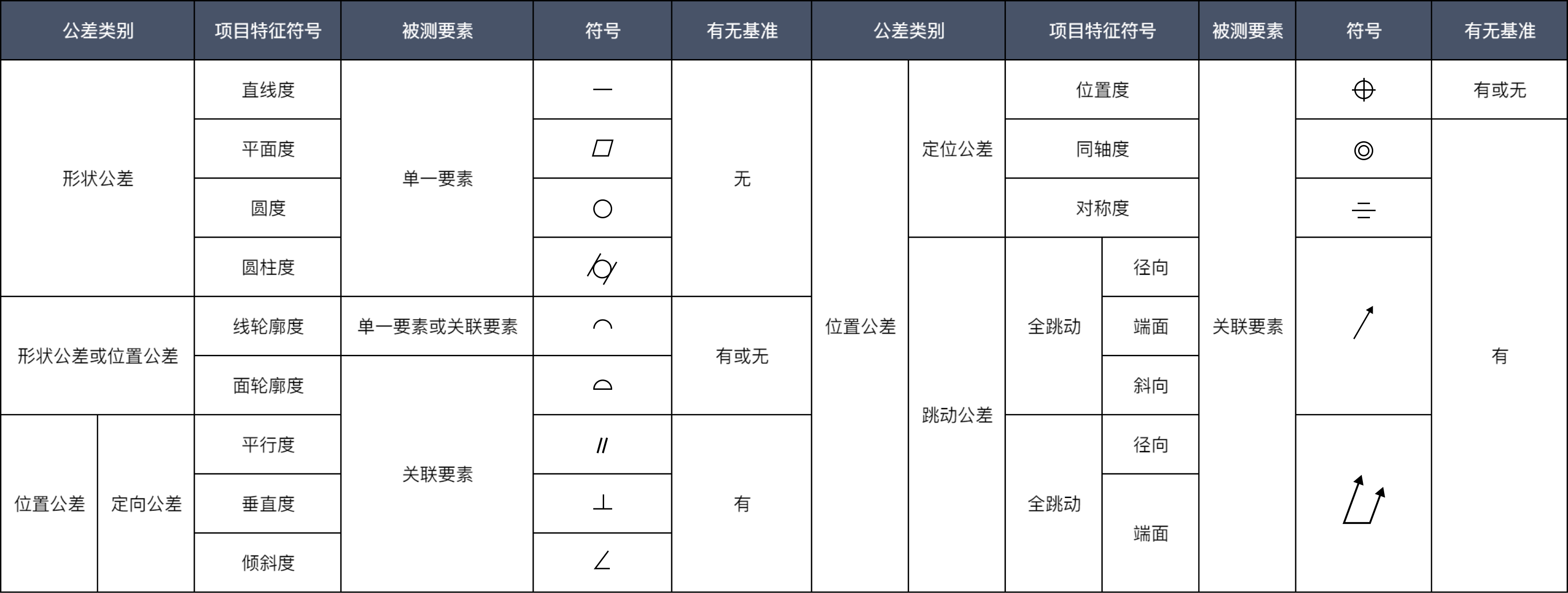
6. Shape and position tolerance
1. Shape and position tolerance, also known as "geometric tolerance" in international standards and national standards, is used to control the actual shape, direction and mutual position of each element on the part relative to the ideal shape, direction and mutual position degree of deviation to ensure the geometric accuracy of the part.
2. Classification and basic symbols of morphological and positional tolerances;