
17
2025.3
author
192
Reading volume
How the milling cutter cuts into the workpiece is crucial for machining. Cutting into the part or improperly cutting into the part can damage the workpiece. Below, we'll explore the most common cutter cutting methods, as well as tips on how to use them.
OnePre-drilled
Pre-drilling a hole into the workpiece (5-10% larger than the end mill diameter) is the safest way to cut the mill. This method avoids premature tool wear. Smoother chip evacuation, which reduces the risk of chip build-up and tool breakage. This method is often used when machining materials prone to edge buildup, ensuring consistent machinability. Common tool materials in tool grinding include: high-speed steel, powder metallurgy high-speed steel, cemented carbide and superhard materials such as PCD, CBN, and cermet. High-speed steel tools are sharp and have good toughness, while carbide tools have high hardness but poor toughness. The density of carbide tools is significantly greater than that of high-speed steel tools. These two materials are the main materials for drills, winches, milling cutters and taps. The properties of powder metallurgy high-speed steel are between the above two materials, and are mainly used to make rough milling cutters and taps. HSS tools are less sensitive to collisions due to their good toughness. However, carbide tools are hard and brittle, sensitive to collisions, and easy to jump. Therefore, in the process of grinding, the operation and placement of carbide tools must be very careful to prevent collisions between tools or knives falling. Because the accuracy of high-speed steel tools is relatively low, their grinding requirements are not high, and their prices are not high, so many manufacturing plants set up their own tool workshops to repair them. However, carbide tools often need to be sent to a professional grinding center for regrinding. According to the statistics of some domestic tool repair centers, more than 80% of the tools sent for repair are cemented carbide tools.
TwoScrew feed
Spiral feeding is a very common and safe way to feed the tool. Using a fillet radius mill during operation can reduce tool wear and mitigate tool breakage. When using this method, the diameter should be greater than 110-120% of the diameter of the cutting blade when programmed. Additionally, auger feeders offer advantages in achieving precise surface finishes, making them a preferred choice for machining that requires high precision and surface quality, such as aerospace and medical device manufacturing.
ThreeOblique insertion type of feeder
This method of feeding is largely flawless, but applies a variety of torsional forces to the tool. Therefore, the key to adopting this method is to have a good knife with sufficient strength and easy chip removal. Using a tool with a rounded radius enhances the strength of its cutting parts. Additionally, the oblique feeder efficiently removes material with reduced axial forces, minimizing workpiece deformation and improving dimensional accuracy. This method is often employed by machinists in contouring and grooving, as it is crucial for maintaining the integrity of the workpiece.
Suggested angle:
Rigid/ferromagnetic material: 1°-3°
Plastic/non-ferromagnetic materials: 3°-10°
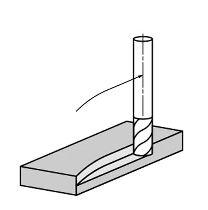
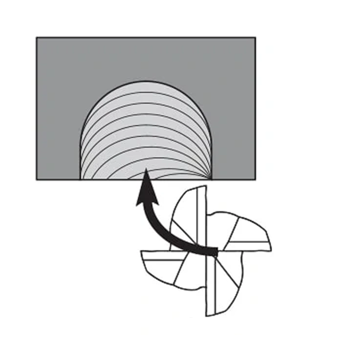
FourArc cut
This method of cutting the tool is similar in method and effect to the diagonal cutting. However, bevel cuts enter the part from the top, while arc cuts enter from the sides. During milling, the end mill moves along a curved toolpath or arc, which allows it to gradually increase the load on the tool as it enters the part. Additionally, the load applied to the tool decreases as it leaves the part, helping to avoid shock loading and tool breakage. Machinists often use this technique in mold making, die settling, and 3D contouring operations to improve productivity and surface finish quality.
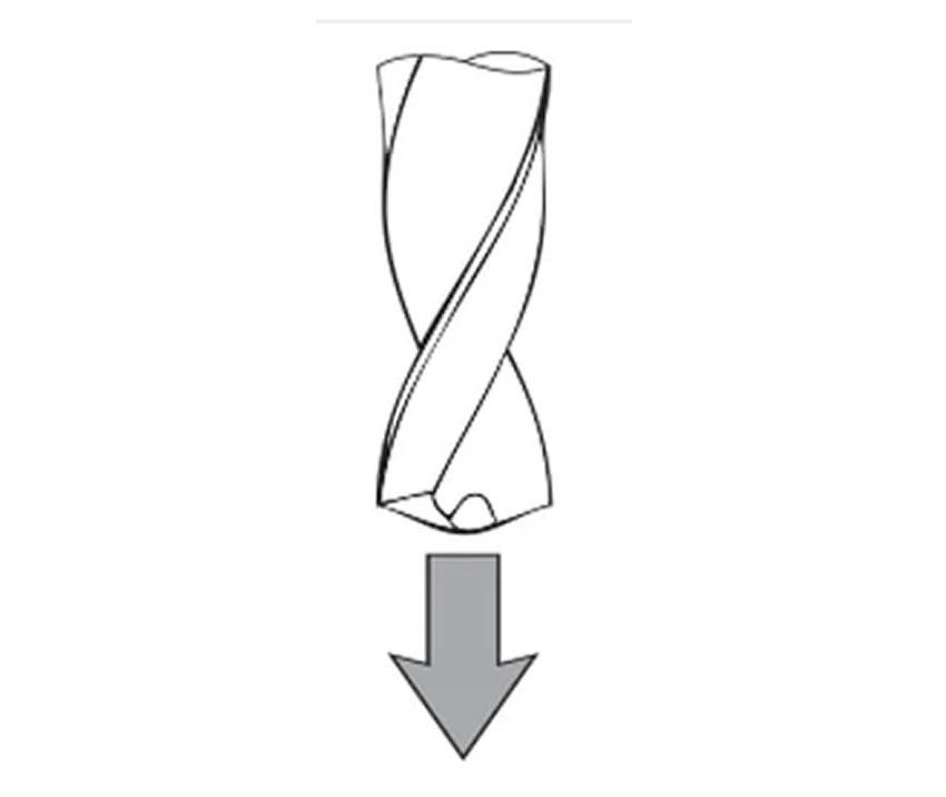
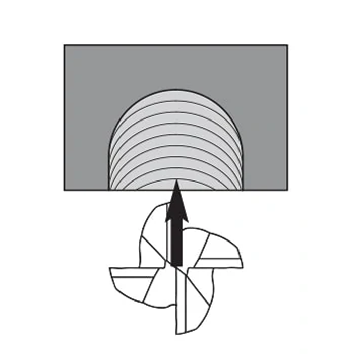
Cut directly down
This is a common but often problematic path. Cutting directly into the part can easily lead to tool breakage. However, if this method is chosen, some conditions must be met to improve the chances of successful machining. The tool must be center-cut, as face milling uses a straight entrance, making chip evacuation extremely difficult. The drill is designed for direct cut, so direct cutting is used for this type of operation.
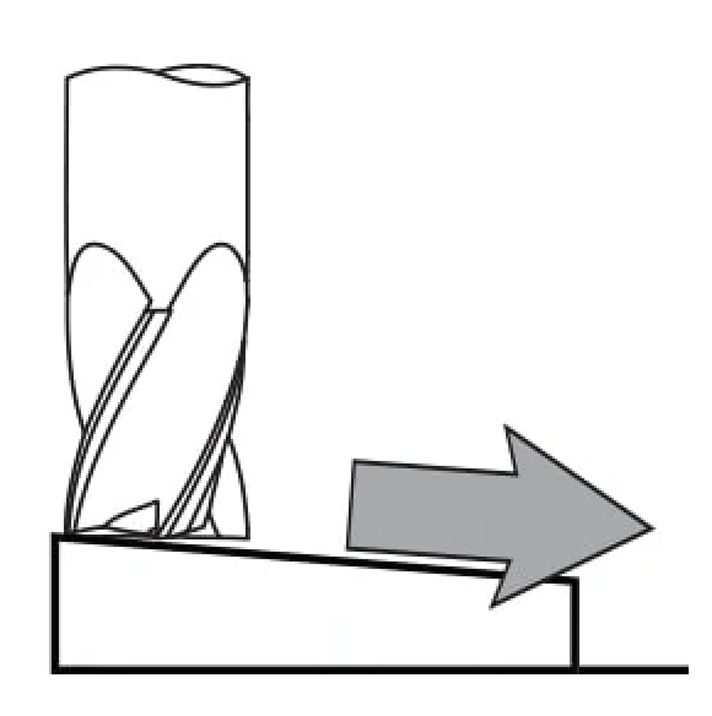
Straight knife side cut
The side cut parts wear more on the tool, just like direct drilling. It is recommended to reduce the feed rate by at least 50% during operation before the tool is fully cut. Machining masters usually use the straight cutter cutting method in simple cutting operations, which is relatively direct and simple, and can effectively solve the problem of tool cutting difficulties when meeting certain machining accuracy requirements. However, monitor tool wear and chip evacuation to prevent chip buildup and tool breakage. Adjusting cutting parameters based on material properties and part geometry can further improve machining efficiency and tool life.
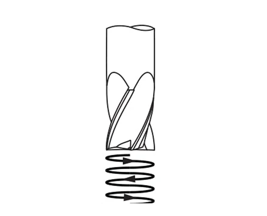
FiveRoll cut
Roll-in cutting ensures that the tool can cut fully and naturally achieve the appropriate chip thickness. In this case, the feed rate should be reduced by 50%. Rolling tool cutting is particularly advantageous in grooving and contouring, where maintaining consistent chip thickness is crucial for surface finish and dimensional accuracy. Machinists are often used in high-speed cutting operations to maximize material removal rates while minimizing tool wear and heat generation.
Mastering various tool entry methods is crucial for machining. By understanding and implementing these methods effectively, performance can be optimized and tool lifespan can be extended.